What Is Radiosity?
Posted on Tue 13 October 2026 in tech
Radiosity renders the light that bounces off matte surfaces.
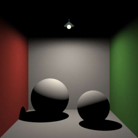
Since light from the bulb is focused downward, none of it reaches the ceiling directly. This is a problem because a ray tracer, which does not see indirect light, paints that ceiling black.
| Direct light | Radiosity |
|---|---|
 |
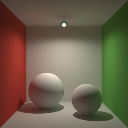 |
The left render, lit like my old college dormitory, depicts only light that arrives straight from the bulb. Radiosity, on the right, adds the light that bounces off the floor and walls.
A ray tracer limits the paths it follows. When a ray hits matte paint, the
tracer asks each lamp whether it can see that point and stops, so light
bouncing off the paint never arrives. In a real room, light leaving matte
paint scatters in every direction. A path tracer follows it with a fan of rays
at every hit and pays in render time and noise. What Is Ray
Tracing? stopped here, with a constant
ambientlight standing in for all that bounced light. Radiosity computes the
bounced light once for the whole scene, and every camera reuses the result.
A Hilbert wall
A matte wall is a light source of its own. Every point the light strikes sends part of it back out in every direction, and that light reaches every other surface in the room. That makes an infinity of directions at each of an infinity of points, a Hilbert wall if you will. A 60-watt bulb puts out on the order of 1019 visible photons each second. At the scale our eyes perceive, the glow from a wall is overwhelmingly diffuse. A red wall lights the sphere beside it red because that glow reaches the sphere from every point on the wall at once.
An algorithm that casts individual rays can only ever be a limited proxy for these infinities. The renders above stand in for them with about 1.8 million camera rays, 450 × 450 pixels at 9 samples each. Each is at best an approximation of the light the eye would see.
How much does the bouncing add? Put a lamp in a closed room painted white. White paint reflects about 80 percent of the light that reaches it, so each trip across the room delivers four fifths of the trip before. The walls end up with the direct light times
1 + 0.8 + 0.8² + 0.8³ + ⋯ = 1 / (1 − 0.8) = 5The walls shine five times brighter than the lamp alone makes them, and four fifths of what they receive has bounced at least once. For walls of reflectance ρ the sum is 1 / (1 − ρ), and the bounced share is ρ itself.
Where the light lands
Take one small patch of wall. Of the light it sends out, some fraction lands on a given patch across the room. That fraction is the form factor, and three things set it:
- Distance. A patch twice as far away looks a quarter the size and catches a quarter of the light.
- Tilt, at both ends. A surface sends the most light straight out from its face and none along it, and a patch catches the most face-on and none edge-on.
- Whatever is in the way. A blocked patch catches nothing.
The light has to land somewhere, so in a closed room a patch's form factors add up to 1. A form factor is pure geometry, fixed by where the two patches sit, which way they face and what stands between them. For a small patch of area A at distance r, with each end tilted by its angle θ from facing the other:
F = cos θsend × cos θreceive × A / (π r²)The π is the area of a circle of radius 1. Cover the sending patch with a dome of radius 1 and project the receiving patch onto it; distance and the receiving tilt shrink its image to cos θreceive × A / r². Press that image flat onto the dome's floor, and the sending tilt shrinks it again by cos θsend. The form factor is the share of the floor it covers. Everything the patch sees covers that floor exactly once, so the shares add up to 1. Nusselt (1928) drew this construction for radiant heat.
Inside a sphere, distance and tilt cancel. The chord between two points on a sphere of radius R meets the wall at the same angle θ at both ends, and its length is r = 2R cos θ. The form factor becomes cos² θ × A / (π × 4R² cos² θ) = A / (4πR²): the patch's share of the sphere's area, wherever it sits. Light a closed sphere from its centre and every point on the wall receives the same bounce light, ρ / (1 − ρ) times the direct light: the bounced part of the white room's sum. That uniform answer is an exact test for both the radiosity solver and the path tracer.
One equation carries the bounces and the form factors for every patch at once. Patch i sends out the light it makes plus ρ of the light that lands on it:
Pi = Ei + ρi × Σj Fji × PjFji is the fraction of patch j's light that lands on patch i. The light a patch sends out per unit area, Pi divided by its area, is its radiosity, the quantity the method is named for. Substitute the equation into itself and each substitution adds one bounce: the series 1 + ρ + ρ² + ⋯ again, with the geometry carried along.
A matte patch looks equally bright from every direction, so one number describes it and the solution holds for every viewpoint.
Cornell box
The radiosity equation began in heat transfer, where engineers use it for radiant heat exchanged between surfaces and call F the view factor. Goral, Torrance, Greenberg and Battaile (1984), at Cornell, applied it to light and rendered a box with coloured walls. The box above descends from theirs, and graphics researchers have tested renderers against a Cornell box ever since.
A direct solution needs a form factor for every pair of patches that see each other, at most n²: 100 million for 10,000 patches. Cohen, Chen, Wallace and Greenberg (1988) replaced it with progressive refinement. Each step picks the patch holding the most light it has yet to pass on and shoots that light to every other patch. The largest contributions arrive first, so the image is usable after a few steps and improves with each one.
Radiosity handles diffuse surfaces only. A mirror's brightness depends on the viewing direction, and a patch stores one number. Wallace, Cohen and Greenberg (1987) combined the two methods: radiosity for light scattered between diffuse surfaces, ray tracing for reflection and refraction.
How the solver works
The implementation follows the 1987 two-pass design and runs progressive refinement inside the ray tracer:
- The ray tracer computes direct light, so each patch starts with ρ times its direct light as unshot light, and the lights themselves never shoot.
- Each step shoots from the patch with the most unshot power, its unshot light times its area.
- Shadow rays give the form factors, by the disc approximation of Wallace, Elmquist and Haines (1989). Each shooting patch is sampled at 16 points, and a ray from the receiving patch to each point tests visibility. A translucent surface in the way transmits a share 1 − Os.
- Shooting stops when the unshot power falls to a thousandth of the direct power.
- At render time,
ambient()adds each point's bounce light, scaled by the surface'sKa.
On an Apple M3 Max the box renders in 1.3 seconds with direct light only and in 17 seconds with the radiosity pass.
Try it
Install gman with the tarball's install.sh, as the README shows. Then download box.rib and render it:
gman -r gmanraytracer box.rib
That writes box.png, the right-hand render. For the left, delete the two Option lines and set the first Ka to 0. Option "radiosity" "float elementsize" [0.15] sets the patch size; without it the patch size defaults to an eighth of the scene's largest side, 0.25 here, and the box renders in 3.6 seconds. Smaller patches resolve finer shadows and take longer.
In the file, a spotlight just under the bulb carries all the light in the room and shines only below the shade's rim. The bulb, its shade and its cord show by ambientlights scoped to them, which the radiosity pass leaves out of its direct light.
Then repaint the white surfaces: change both Color [0.725 0.725 0.725] lines to [0.9 0.9 0.9]. The paint reflects 24 percent more light, and the ceiling, lit by bounce alone, gets 70 percent more, because every bounce compounds the change. On screen the step looks smaller, squeezed by the display gamma that Exposure 1.05 2.2 applies.
One equation, two ways to solve it
The patch equation is a special case of the one What Is Ray Tracing? unrolls in its section "One term per bounce". Drop the patches and the matte surfaces, and let L be the light travelling in every direction from every point, Le the light the sources emit and K the operator that carries light one bounce across the scene:
L = Le + K*LKajiya (1986) wrote it down as the rendering equation. Each bounce's light is K applied to the bounce before, Ln+1 = K*Ln, starting from L0 = Le, and L is the sum of every bounce. In the white room, K multiplies by 0.8, so Ln = 0.8n L0, and the sum is the series 1 + 0.8 + 0.8² + ⋯ from the white room above.
A ray tracer evaluates the rendering equation one term at a time, but only along mirrors and glass. To evaluate every term, a renderer takes one of two approaches. A solver, which is what radiosity is, cuts the scene into patches, turns K into a table of form factors and computes the answer deterministically. Its error is the patch size: detail smaller than a patch blurs.
Monte Carlo estimates the same sum by averaging random samples: follow one random path of light bounce by bounce, then another, and average them. Its error is noise, which falls as one over the square root of the number of paths, so four times the paths halves it. A path tracer is Monte Carlo on the rendering equation. The next article in this series covers path tracing, which renders this box the other way so each answer checks the other.
Links
- gman on GitHub, with its releases and changelog
- The gman page